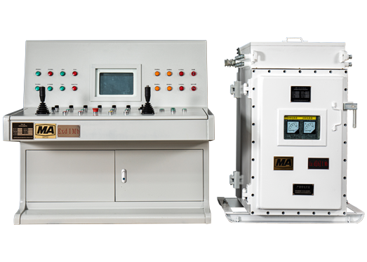
The device is combined with various VFDs for mining applications to form a mine hoist frequency conversion control system, which is suitable for underground coal mines and other locations containing coal dust, gas or other flammable and explosive gases. This includes inclined underground shafts, single level, multi-level, single-drum, and double-drum mine hoists.
1. Conforms to all safety protection requirements stipulated in the Coal Mining Safety Regulations;
2. Fully Chinese/English/ Vietnamese HMI, operating parameters and fault descriptions all in native language, easy to use, maintain and repair;
3. Using advanced vector /DTC control technology, the system features high precision speed regulation, good speed regulation performance and good mechanical characteristics.
4. The active front-end rectifier (AFE) feedback technology ensures electrical braking with regenerative energy feedback, high braking torque, high power factor and good response characteristics.
5. High-performance dual PLC is configured to form the parallel control and protection system, while hardware and software redundancy design are adopted for key circuits, such as safety shutdown loops and speed protection loops, to achieve double or triple protection;
6. The system is designed and evaluated in accordance with the principles of safety and reliability, advanced technology, easy operation and maintenance, cost-savings and practicality;
7. Basically maintenance-free, significantly reducing equipment downtime due to maintenance;
8. Complete commissioning services are provided, while the EMC (Electromagnetic Compatibility) of the system meets all requirements of the national and IEC standards;
9. All equipment and related products feature the Safety Mark Certificate for Mining Applications and compulsory 3C Certificate for Industrial Products;

1. The neutral position of the operating handle is interlocked with the safety circuit;
2. The emergency stop button on the operating console is interlocked with the safety circuit;
3. The emergency stop of the signaling system is interlocked with the safety circuit;
4. Allows the start signal to interlock with the hoist start circuit;
5. Signal system lockout in the driving direction;
6. The hydraulic station motor is interlocked with the hoist safety circuit;
7. The lubrication station motor is interlocked with the hoist running circuit;
8. Lockout in the overwinding direction and the driving direction;
9. The power-on circuit is interlocked with the safety circuit;
10. Lockout of the upstream feeder switch and safety circuit;
11. The inclined slope stopper is interlocked with the safety circuit;
12. Lockout for operating procedure.
1. Software and hardware over-winding protection
2. Overspeed protection in constant speed section
3. Overspeed protection in deceleration section
4. Hardware overspeed protection
5. Foreshaft 2m/s speed limit protection
6. Speed deviation protection
7. Speed sensor failure protection
8. Depth indicator failure protection
9. Incorrect direction protection
10. Loose rope protection
11. Full storage protection
12. Brake wear protection
13. Hydraulic station oil over-pressure protection
14. Hydraulic station residual over-pressure protection
15. Lubrication station under-pressure protection
16. Temperature protection for hydraulic station and main motor
17. Transmission system failure protection
18. Clutch failure protection
19. Automatic deceleration alarm at deceleration point
20. Foreshaft automatic secondary brake disable function


